[View 26+] Draw The Schematic Diagram Given The Figures Below
View Images Library Photos and Pictures. Design Handbook Engineering Drawing And Sketching Related Resources Design And Manufacturing I Mechanical Engineering Mit Opencourseware E2 Lab 2 State Tables And State Diagrams The Schematic Diagram A Basic Element Of Circuit Design Analog Devices

. Automatic Irrigation System Mechatronics Exercises Aalto University Wiki Central Air Conditioning Systems And Applications Intechopen With The Help Of A Diagram Derive The Formula For The Resultant Resistance Of Three Resistors Connected In Series Studyrankersonline
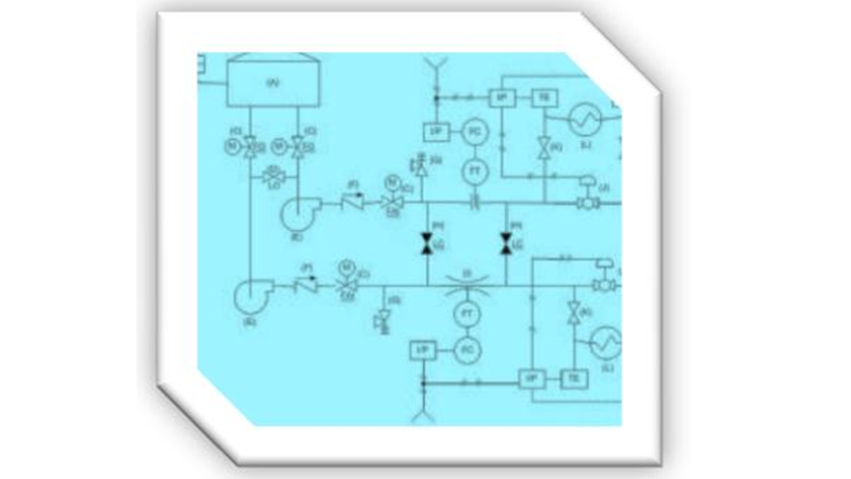
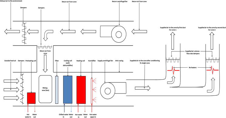 Central Air Conditioning Systems And Applications Intechopen
Central Air Conditioning Systems And Applications Intechopen

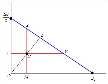 Safety Factor
 Ans This Plz 29 For The Given Circuit Shown In Figure Below Time Constant Is A Physics Current Electricity 12832595 Meritnation Com
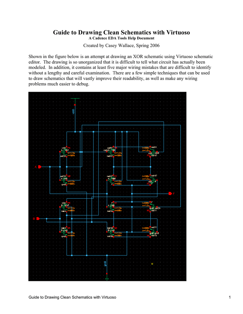 Guide To Drawing Clean Schematics With Virtuoso
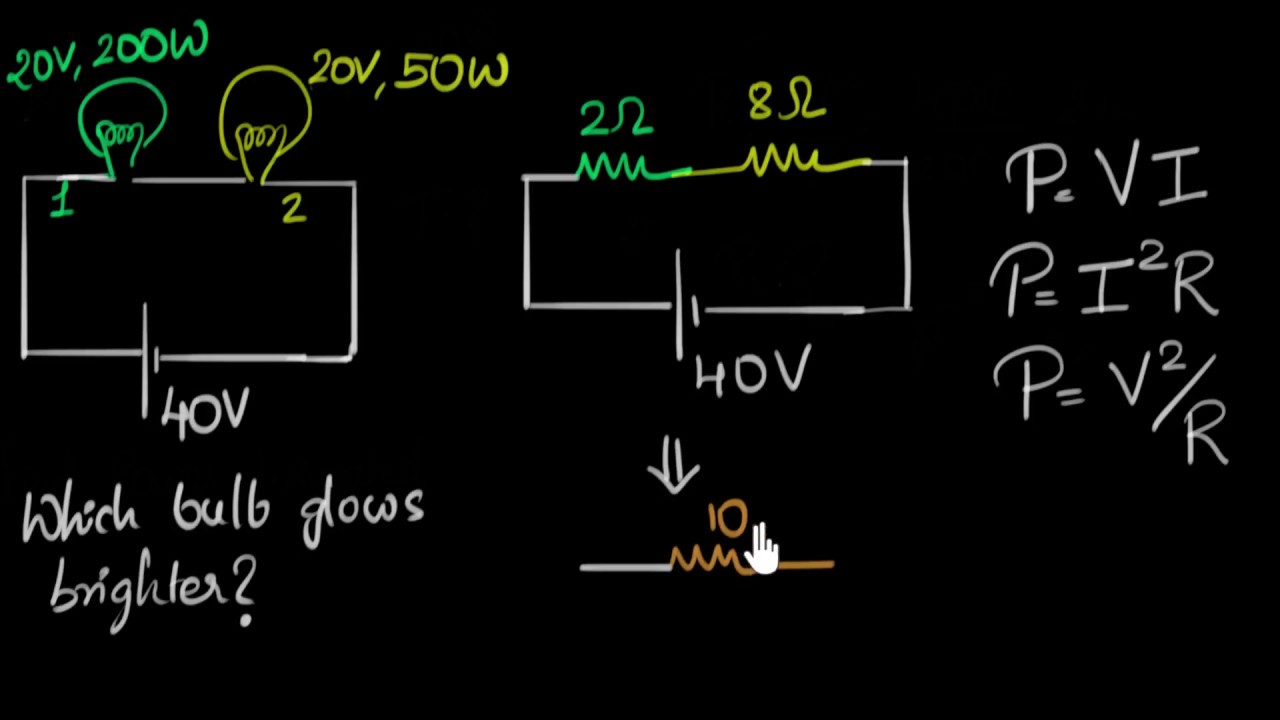 Solved Example Power Dissipated In Bulbs Video Khan Academy
 How To Draw An Electronic Schematic Youtube
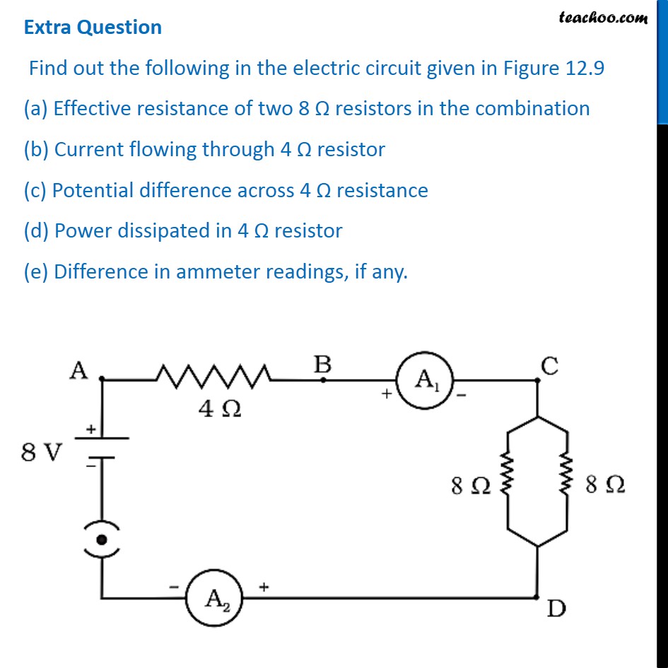 Practice Problems For Electricity Class 10 Teachoo Science
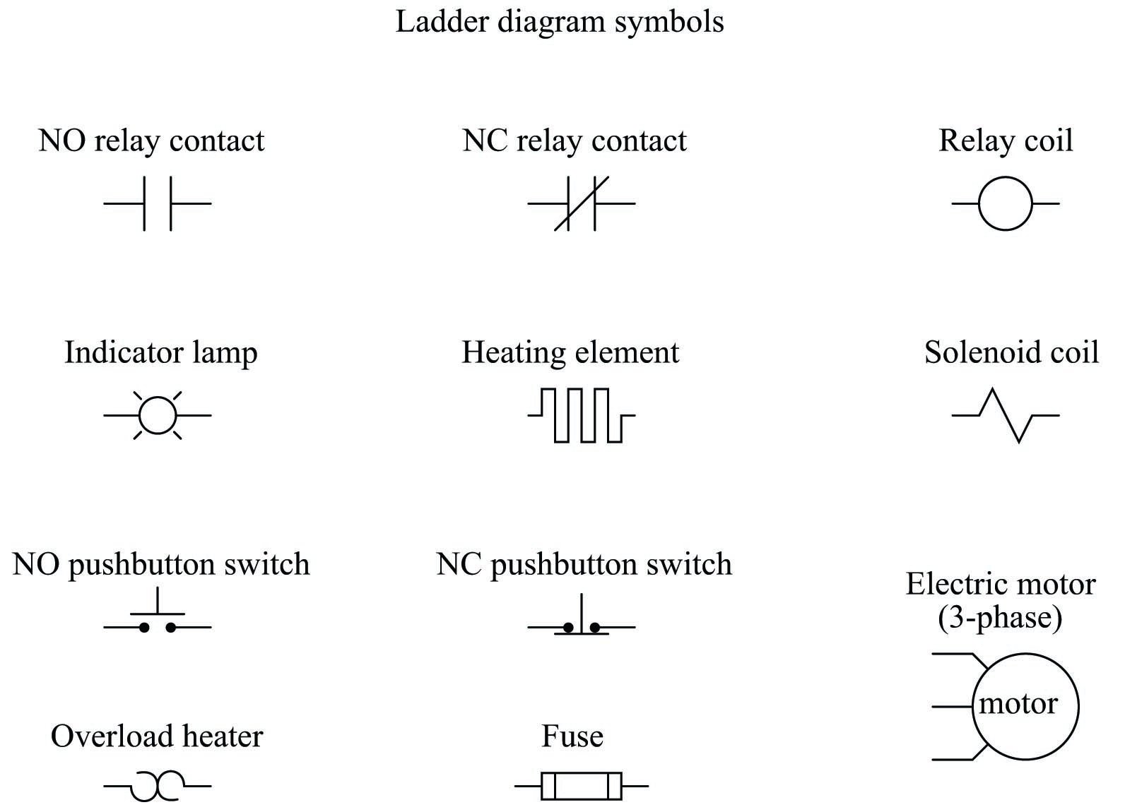 Relay Circuits And Ladder Diagrams Relay Control Systems Automation Textbook
 Organization Of Computer Systems Processor Datapath
 Lakhmir Singh Physics Class 10 Solutions For Chapter 1 Electricity Free Pdf
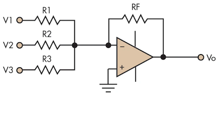 Efficiently Design An Op Amp Summer Circuit Electronic Design
Draw The Schematic Diagram Given The Figures Below Brainly Ph
 Planet Analog When Gnd Isn T Gnd Single Ended Circuits Become Differential
 Interpreting Piping And Instrumentation Diagrams Symbology Aiche
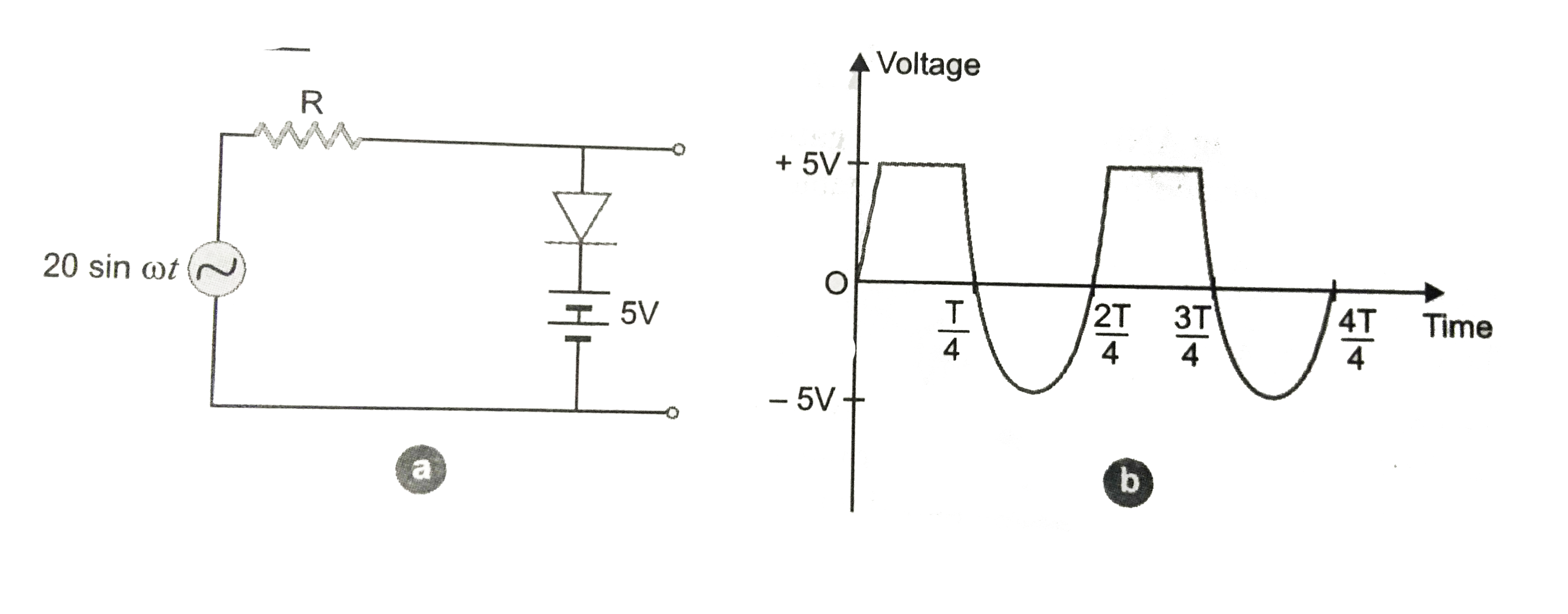 The Output Of The Given Circuit In Figure Given Below Br Img S
Gate1996 24 A Gate Overflow
 A Circuit Is Shown In The Diagram Given Below A Find The Value Of R B Find The Science Electricity 9455821 Meritnation Com
 Parallel Rlc Circuit And Rlc Parallel Circuit Analysis
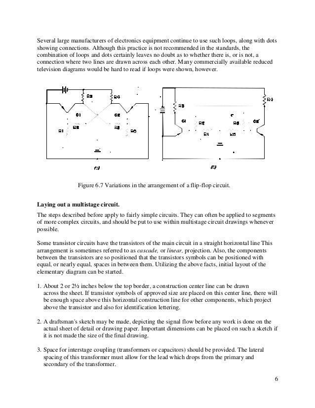 Schematic Diagrams
 Electrical Drawings And Schematics Overview
 Network Diagram Guide Learn How To Draw Network Diagrams Like A Pro
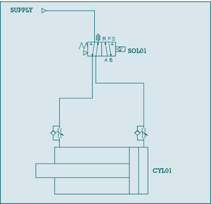 Basic Pneumatic Circuits Part 2 Of 2 Modern Pumping Today
 How To Make A Schematic Diagram In Coreldraw
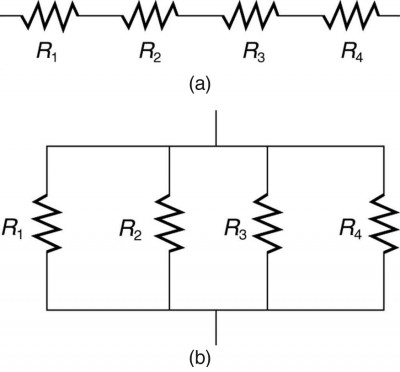 Resistors In Series And Parallel Physics
Solved Draw The Shear Force Bending Moment Diagrams Of The Beam Shown In The Figure Below Taking Into Account The Given Loading Make Detailed Cal Course Hero
 The Logic Circuit Shown In The Figure Below Is Used To Activate An Alarm When Its Output Y Is Logic High Or 1 Draw A Truth Table For The Circuit Showing The
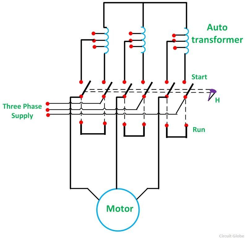 What Is Auto Transformer Starter Its Theory Circuit Globe
Comments
Post a Comment